-
5.0 Stars ⭐⭐⭐⭐⭐ 628 Google Reviews


DamasoSanoja
-
Posts
38 -
Joined
-
Last visited
-
Carnity Points
0 [ Donate ]
DamasoSanoja's Achievements
")
New Joiner (1/14)
0
Reputation
-

 What does this OBD II code mean? This generic OBD2 code is set when the Powertrain Control Module (PCM) detects a short circuit in the reductant injection valve. This particular code is pointing out the bank 2, in other words, the bank of cylinders not containing cylinder #1. The unit 2 tag is indicating that more than one injector is used for the bank 2. Why does this OBD II code appear? On modern diesel engines, the use of an Exhaust Recirculation Valve (EGR) is not enough to fully control the amount of NOx present in the exhaust gases. That’s why the use of reductant injection systems is necessary. This system consists of one or more injectors (solenoids) commanded by the PCM that sprays a diesel exhaust fluid (DEF) just before the diesel particulate filter which in turn is part of the Selective Catalyst Reduction (SCR) system. The fluid elevates the temperature of the filter element increasing its efficiency and longevity. The injection valve solenoid only operates under certain conditions though. It’s the job of the PCM/SCR module activating this solenoid after analyzing the information from its sensors and hence helping to transform the harmful NOx emissions to nitrogen, carbon dioxide, and water. The OBD2 code P2058 is stored in memory when the PCM detects a short circuit in the solenoid valve (a voltage higher than expected). What symptoms may occur with this OBD II code? Expect the typical symptoms from a P2058 condition: CEL lit. The Check Engine Light will turn on after few driving cycles to alert the driver about the situation. Possible decrease in fuel economy. Black smoke coming from the tailpipe due to NOx leftovers. What are the causes that trigger this OBD II code? There're many factors that could cause a P2058 condition including among others the following: Damaged, burnt, corroded, open or shorted injector valve wiring. Worn, corroded, burnt, disconnected or bent wiring harness connector pins. Faulty or deficient DEF injector valve solenoid. Even when unlikely, a defective PCM cannot be discarded. Please notice that possible causes are based on the assumption that only trouble code P2058 is stored in memory. Diagnostic strategy for troubleshooting this OBD II code Warning: If any other code directly related with temperature, vacuum or throttle position sensor is present then you must start diagnosing and solving those codes first. It's highly recommended starting the diagnostic process with the usual information gathering: With the help of a professional OBD2 scan tool, preferably one with OEM capabilities, take note of all data trouble codes in memory, including pending codes. Take note of freeze frame information (if present). Query the vehicle owner about what, when and where the failure occurs. Does it happen with the engine hot? Cold? Under load? All the standard questions. Take note of the vehicle VIN and find a reliable source of technical reference. Once you are done, the next step is discarding an intermittent condition. Using your scan tool clear DTC memory. Perform a complete driving cycle according to OEM procedures. If the code P2058 disappears then inform the owner about the intermittent nature of the code and explain that further testing with the code present will be required. If the code does appear then continue to the testing stage, consisting in discarding the possible causes of the problem. IMPORTANT: the diagnostic procedure explained in this section should be taken as a guideline. Always refer to specific OEM procedures when possible. The workflow for the diagnostic process is: The tests should be executed in sequential order, in other words, complete step 1 before going to step 2 and so on. Repair, fix, or replace any component if you suspect is not in good condition. If any repair, fix, reprogramming or component replacement is made during any step then you should clear DTC memory and repeat the whole KOER driving cycle. If the DTC appear again then you should continue to the next step. If the DTC does not appear again after completing the KOER tests then you can assume the problem is fixed, in that case, continuing with the remaining steps would be optional. The diagnostic process for the code P2058 is as follows: Sensor harness wiring and connector: carry out an exhaustive visual inspection of bank 2 DEF solenoid wiring and connectors. Pay special attention to burnt, corroded, open, shorted to ground or deteriorated wiring and/or connector. Unplug the solenoid and check for corrosion, damage, bent pins, etc. Electrical tests: with the help of a digital volt-ohm meter (DVOM) and the adequate wiring diagram perform a KOEO check on the DEF solenoid. Verify supply and/or reference voltage, electrical resistance, continuity, current and ground integrity. Compare the obtained values with the appropriate OEM literature. Problems with the powertrain control module: the most unlikely cause for this code is a faulty PCM or SCR module. Yet, if you are completely certain that all prior tests passed then you must remove the PCM/SCR module and check it, reprogram it or replace it as necessary. Do you need further help....? Discuss your car trouble code further with thousand's of car experts here Check your car problem in Vehicle Recall Section of your car brand
 -
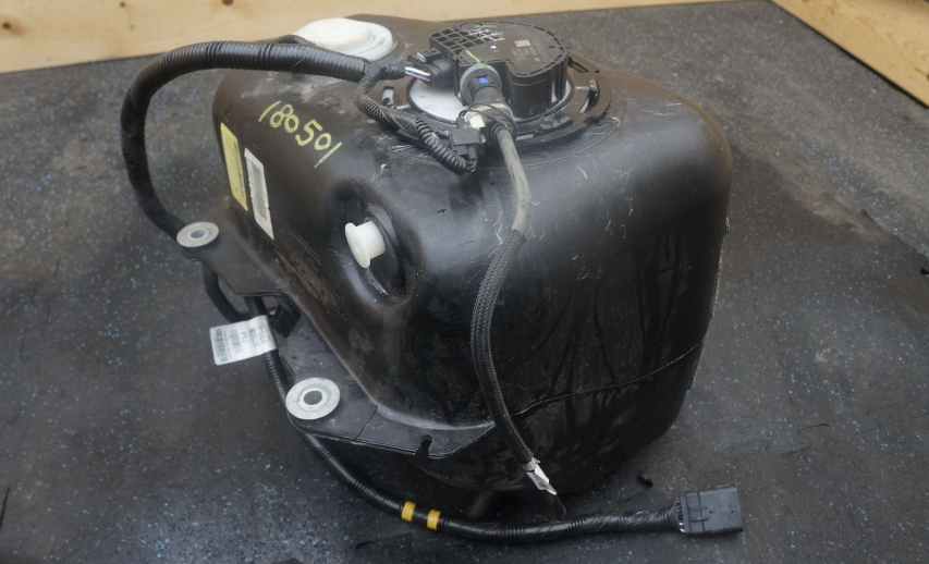
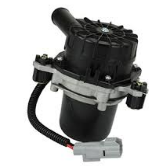
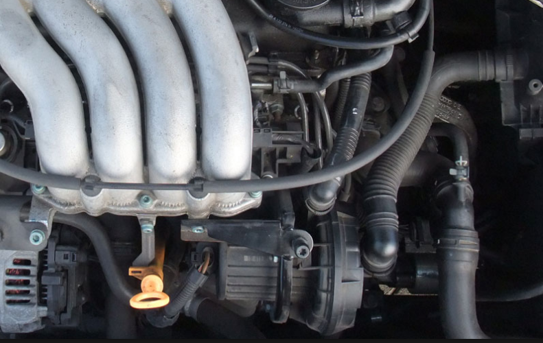
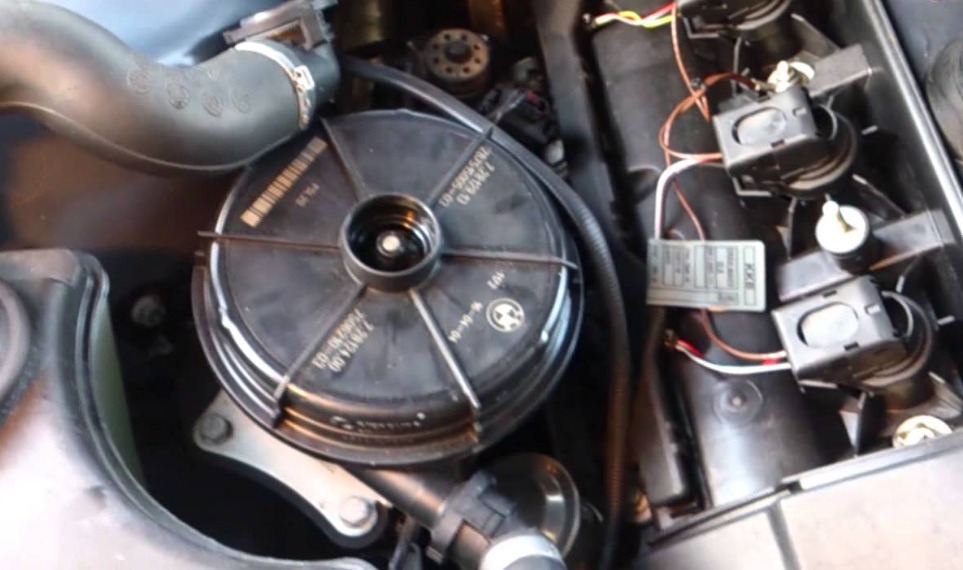 What does this OBD II code mean? This generic OBD2 code is set when the Powertrain Control Module (PCM) senses a possible short circuit in the Secondary Air Injection System (AIR) pressure sensor circuit. This particular code is pointing out the bank 1, in other words, the bank of cylinders containing cylinder #1. Why does this OBD II code appear? The objective of the Secondary Air Injection System (AIR) is decreasing the hydrocarbon emissions under certain conditions. In order to accomplish that goal AIR inject fresh air to the exhaust system using an air pump. Besides the air pump, the AIR system uses one or more actuators (valves or solenoids) to divert the air stream as well as a pressure sensor. The OBD2 code P2430 is stored in memory when the PCM suspects of a short circuit in the AIR pressure sensor. What symptoms may occur with this OBD II code? Expect the typical symptoms from a P2430 condition: CEL lit. The Check Engine Light will turn on after few driving cycles to alert the driver about the situation. The engine may die during idle. Possible hesitation during idle or while accelerating. Possible noise from the AIR system. What are the causes that trigger this OBD II code? There're many factors that could cause a P2430 condition including among others the following: Damaged, burnt, corroded, open or shorted AIR pressure sensor. Worn, corroded, burnt, disconnected or bent AIR pressure sensor wiring harness connector pins. Faulty or deficient AIR pressure sensor. Faulty or deficient AIR solenoids. Faulty or deficient air pump. Even when unlikely, a defective PCM cannot be discarded. Diagnostic strategy for troubleshooting this OBD II code It's highly recommended starting the diagnostic process with the usual information gathering: With the help of a professional OBD2 scan tool, preferably one with OEM capabilities, take note of all data trouble codes in memory, including pending codes. Take note of freeze frame information (if present). Query the vehicle owner about what, when and where the failure occurs. Does it happen with the engine hot? Cold? Under load? All the standard questions. Take note of the vehicle VIN and find a reliable source of technical reference. Once you are done, the next step is discarding an intermittent condition. Using your scan tool clear DTC memory. Perform a complete driving cycle according to OEM procedures. If the code P2430 disappears then inform the owner about the intermittent nature of the code and explain that further testing with the code present will be required. If the code does appear then continue to the testing stage, consisting in discarding the possible causes of the problem. IMPORTANT: the diagnostic procedure explained in this section should be taken as a guideline. Always refer to specific OEM procedures when possible. The workflow for the diagnostic process is: The tests should be executed in sequential order, in other words, complete step 1 before going to step 2 and so on. Repair, fix, or replace any component if you suspect is not in good condition. If any repair, fix, reprogramming or component replacement is made during any step then you should clear DTC memory and repeat the whole KOER driving cycle. If the DTC appear again then you should continue to the next step. If the DTC does not appear again after completing the KOER tests then you can assume the problem is fixed, in that case, continuing with the remaining steps would be optional. The diagnostic process for the code P2430 is as follows: Sensor harness wiring and connector: carry out an exhaustive visual inspection of AIR pressure sensor wiring and connectors. Pay special attention to burnt, corroded, open, shorted to ground or deteriorated wiring and/or connector. Unplug the sensor and check for corrosion, damage, bent pins, etc. Electrical tests: with the help of a digital volt-ohm meter (DVOM) and the adequate wiring diagram perform a KOEO and KOER check on the AIR pressure sensor. Verify supply and/or reference voltage, electrical resistance, continuity, current and ground integrity. Compare the obtained values with the appropriate OEM literature. AIR pressure sensor: using a scan tool you can check the sensor output. With the help of a manual vacuum pump perform a KOEO test to check its condition. Replace as necessary. AIR system functional test: some manufacturers include built-in tests that help in the process of diagnosing the AIR system, others not. Refer to the proper literature in order to perform a complete system diagnostic. The test allows you to manipulate the solenoids and air pump activation. Replace if needed. Problems with the powertrain control module: the most unlikely cause for this code is a faulty PCM or a corrupted program. Yet, if you are completely certain that all prior tests passed then you must remove the PCM and check it, reprogram it or replace it as necessary. Do you need further help....? Discuss your car trouble code further with thousand's of car experts here Check your car problem in Vehicle Recall Section of your car brand
 -
 What does this OBD II code mean? This generic OBD2 code is set when the Powertrain Control Module (PCM) senses a voltage lower than expected in the Secondary Air Injection System (AIR) pressure sensor circuit. This particular code is pointing out the bank 2, in other words, the bank of cylinders not containing cylinder #1. Why does this OBD II code appear? The objective of the Secondary Air Injection System (AIR) is decreasing the hydrocarbon emissions under certain conditions. In order to accomplish that goal AIR inject fresh air to the exhaust system using an air pump. Besides the air pump, the AIR system uses one or more actuators (valves or solenoids) to divert the air stream as well as a pressure sensor. The OBD2 code P2437 is stored in memory when the PCM detects an AIR pressure sensor voltage lower than the acceptable limit. What symptoms may occur with this OBD II code? Expect the typical symptoms from a P2437 condition: CEL lit. The Check Engine Light will turn on after few driving cycles to alert the driver about the situation. The engine may die during idle. Possible hesitation during idle or while accelerating. Possible noise from the AIR system. What are the causes that trigger this OBD II code? There're many factors that could cause a P2437 condition including among others the following: Damaged, burnt, corroded, open or shorted AIR pressure sensor. Worn, corroded, burnt, disconnected or bent AIR pressure sensor wiring harness connector pins. Faulty or deficient AIR pressure sensor. Faulty or deficient AIR solenoids. Faulty or deficient air pump. Even when unlikely, a defective PCM cannot be discarded. Diagnostic strategy for troubleshooting this OBD II code It's highly recommended starting the diagnostic process with the usual information gathering: With the help of a professional OBD2 scan tool, preferably one with OEM capabilities, take note of all data trouble codes in memory, including pending codes. Take note of freeze frame information (if present). Query the vehicle owner about what, when and where the failure occurs. Does it happen with the engine hot? Cold? Under load? All the standard questions. Take note of the vehicle VIN and find a reliable source of technical reference. Once you are done, the next step is discarding an intermittent condition. Using your scan tool clear DTC memory. Perform a complete driving cycle according to OEM procedures. If the code P2437 disappears then inform the owner about the intermittent nature of the code and explain that further testing with the code present will be required. If the code does appear then continue to the testing stage, consisting in discarding the possible causes of the problem. IMPORTANT: the diagnostic procedure explained in this section should be taken as a guideline. Always refer to specific OEM procedures when possible. The workflow for the diagnostic process is: The tests should be executed in sequential order, in other words, complete step 1 before going to step 2 and so on. Repair, fix, or replace any component if you suspect is not in good condition. If any repair, fix, reprogramming or component replacement is made during any step then you should clear DTC memory and repeat the whole KOER driving cycle. If the DTC appear again then you should continue to the next step. If the DTC does not appear again after completing the KOER tests then you can assume the problem is fixed, in that case, continuing with the remaining steps would be optional. The diagnostic process for the code P2437 is as follows: Sensor harness wiring and connector: carry out an exhaustive visual inspection of AIR pressure sensor wiring and connectors. Pay special attention to burnt, corroded, open, shorted to ground or deteriorated wiring and/or connector. Unplug the sensor and check for corrosion, damage, bent pins, etc. Electrical tests: with the help of a digital volt-ohm meter (DVOM) and the adequate wiring diagram perform a KOEO and KOER check on the AIR pressure sensor. Verify supply and/or reference voltage, electrical resistance, continuity, current and ground integrity. Compare the obtained values with the appropriate OEM literature. AIR pressure sensor: using a scan tool you can check the sensor output. With the help of a manual vacuum pump perform a KOEO test to check its condition. Replace as necessary. AIR system functional test: some manufacturers include built-in tests that help in the process of diagnosing the AIR system, others not. Refer to the proper literature in order to perform a complete system diagnostic. The test allows you to manipulate the solenoids and air pump activation. Replace if needed. Problems with the powertrain control module: the most unlikely cause for this code is a faulty PCM or a corrupted program. Yet, if you are completely certain that all prior tests passed then you must remove the PCM and check it, reprogram it or replace it as necessary. Do you need further help....? Discuss your car trouble code further with thousand's of car experts here Check your car problem in Vehicle Recall Section of your car brand
 -
 What does this OBD II code mean? This generic OBD2 code is set when the Powertrain Control Module (PCM) senses a voltage, resistance or current outside the expected threshold in the Secondary Air Injection System (AIR) pressure sensor circuit. This particular code is pointing out the bank 2, in other words, the bank of cylinders not containing cylinder #1. Why does this OBD II code appear? The objective of the Secondary Air Injection System (AIR) is decreasing the hydrocarbon emissions under certain conditions. In order to accomplish that goal AIR inject fresh air to the exhaust system using an air pump. Besides the air pump, the AIR system uses one or more actuators (valves or solenoids) to divert the air stream as well as a pressure sensor. The OBD2 code P2436 is stored in memory when the PCM detects an AIR pressure sensor voltage outside its acceptable limit. What symptoms may occur with this OBD II code? Expect the typical symptoms from a P2436 condition: CEL lit. The Check Engine Light will turn on after few driving cycles to alert the driver about the situation. The engine may die during idle. Possible hesitation during idle or while accelerating. Possible noise from the AIR system. What are the causes that trigger this OBD II code? There're many factors that could cause a P2436 condition including among others the following: Damaged, burnt, corroded, open or shorted AIR pressure sensor. Worn, corroded, burnt, disconnected or bent AIR pressure sensor wiring harness connector pins. Faulty or deficient AIR pressure sensor. Faulty or deficient AIR solenoids. Faulty or deficient air pump. Even when unlikely, a defective PCM cannot be discarded. Diagnostic strategy for troubleshooting this OBD II code It's highly recommended starting the diagnostic process with the usual information gathering: With the help of a professional OBD2 scan tool, preferably one with OEM capabilities, take note of all data trouble codes in memory, including pending codes. Take note of freeze frame information (if present). Query the vehicle owner about what, when and where the failure occurs. Does it happen with the engine hot? Cold? Under load? All the standard questions. Take note of the vehicle VIN and find a reliable source of technical reference. Once you are done, the next step is discarding an intermittent condition. Using your scan tool clear DTC memory. Perform a complete driving cycle according to OEM procedures. If the code P2436 disappears then inform the owner about the intermittent nature of the code and explain that further testing with the code present will be required. If the code does appear then continue to the testing stage, consisting in discarding the possible causes of the problem. IMPORTANT: the diagnostic procedure explained in this section should be taken as a guideline. Always refer to specific OEM procedures when possible. The workflow for the diagnostic process is: The tests should be executed in sequential order, in other words, complete step 1 before going to step 2 and so on. Repair, fix, or replace any component if you suspect is not in good condition. If any repair, fix, reprogramming or component replacement is made during any step then you should clear DTC memory and repeat the whole KOER driving cycle. If the DTC appear again then you should continue to the next step. If the DTC does not appear again after completing the KOER tests then you can assume the problem is fixed, in that case, continuing with the remaining steps would be optional. The diagnostic process for the code P2436 is as follows: Sensor harness wiring and connector: carry out an exhaustive visual inspection of AIR pressure sensor wiring and connectors. Pay special attention to burnt, corroded, open, shorted to ground or deteriorated wiring and/or connector. Unplug the sensor and check for corrosion, damage, bent pins, etc. Electrical tests: with the help of a digital volt-ohm meter (DVOM) and the adequate wiring diagram perform a KOEO and KOER check on the AIR pressure sensor. Verify supply and/or reference voltage, electrical resistance, continuity, current and ground integrity. Compare the obtained values with the appropriate OEM literature. AIR pressure sensor: using a scan tool you can check the sensor output. With the help of a manual vacuum pump perform a KOEO test to check its condition. Replace as necessary. AIR system functional test: some manufacturers include built-in tests that help in the process of diagnosing the AIR system, others not. Refer to the proper literature in order to perform a complete system diagnostic. The test allows you to manipulate the solenoids and air pump activation. Replace if needed. Problems with the powertrain control module: the most unlikely cause for this code is a faulty PCM or a corrupted program. Yet, if you are completely certain that all prior tests passed then you must remove the PCM and check it, reprogram it or replace it as necessary. Do you need further help....? Discuss your car trouble code further with thousand's of car experts here Check your car problem in Vehicle Recall Section of your car brand
 -
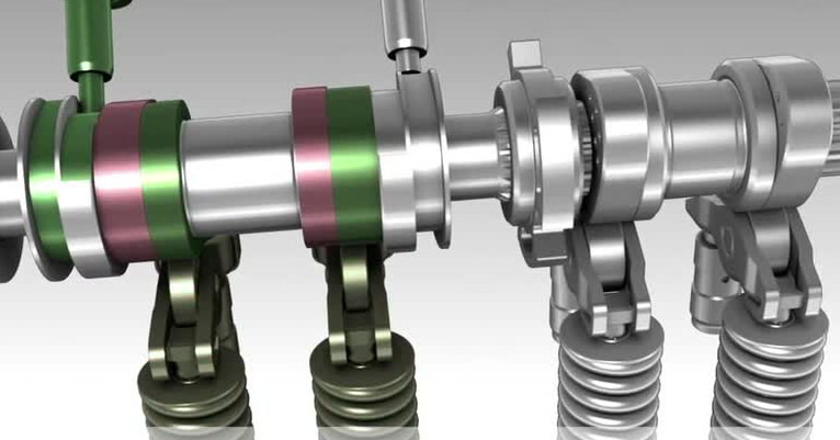 What does this OBD II code mean? This generic OBD2 code is set when the Powertrain Control Module (PCM) senses a problem in the control circuit of the deactivation valve for cylinder #4. Why does this OBD II code appear? Modern “V” type engines, especially V8 engines, implement a strategy known as “cylinder deactivation” to enhance fuel economy. The principle is quite simple, under certain light load conditions the PCM temporarily deactivates up to 4 cylinders, imagine it as a virtual V4 engine. In order to accomplish this functionality, the engine is equipped with variable timing solenoids on the exhaust valves. Depending on the engine firing order the manufacturers configure the system to operate in a way that the driver doesn’t notice any change between modes. Since the PCM is constantly monitoring each exhaust valve control circuit voltage and/or current, any abnormality is noticed immediately. The OBD2 code P3470 is stored in memory when the PCM detects a problem in the control circuit of cylinder 9. What symptoms may occur with this OBD II code? Expect the typical symptoms from a P3470 condition: CEL lit. The Check Engine Light will turn on after few driving cycles to alert the driver about the situation. Poor fuel economy. Possible misfires and/or spark knock. What are the causes that trigger this OBD II code? There're many factors that could cause a P3470 condition including among others the following: Damaged, burnt, corroded, open or shorted solenoid wiring. Worn, corroded, burnt, disconnected or bent wiring harness connector pins. Low engine oil level Low engine oil pressure Clogged oil passage or engine mechanical condition Faulty, deficient variable timing solenoid Even when unlikely, a defective PCM cannot be discarded. Diagnostic strategy for troubleshooting this OBD II code It's highly recommended starting the diagnostic process with the usual information gathering: With the help of a professional OBD2 scan tool, preferably one with OEM capabilities, take note of all data trouble codes in memory, including pending codes. Take note of freeze frame information (if present). Query the vehicle owner about what, when and where the failure occurs. Does it happen with the engine hot? Cold? Under load? All the standard questions. Take note of the vehicle VIN and find a reliable source of technical reference. Once you are done, the next step is discarding an intermittent condition. Using your scan tool clear DTC memory. Perform a complete driving cycle according to OEM procedures. If the code P3470 disappears then inform the owner about the intermittent nature of the code and explain that further testing with the code present will be required. If the code does appear then continue to the testing stage, consisting in discarding the possible causes of the problem. IMPORTANT: the diagnostic procedure explained in this section should be taken as a guideline. Always refer to specific OEM procedures when possible. The workflow for the diagnostic process is: The tests should be executed in sequential order, in other words, complete step 1 before going to step 2 and so on. Repair, fix, or replace any component if you suspect is not in good condition. If any repair, fix, reprogramming or component replacement is made during any step then you should clear DTC memory and repeat the whole KOER driving cycle. If the DTC appear again then you should continue to the next step. If the DTC does not appear again after completing the KOER tests then you can assume the problem is fixed, in that case, continuing with the remaining steps would be optional. The diagnostic process for the code P3470 is as follows: Engine Oil Level and Condition: Verify engine oil condition and level. Perform a complete oil service if necessary. Engine Oil Pressure: using the adequate adapter and engine oil gauge, perform an engine oil pressure test. Refer to the appropriate literature to check results. In order to continue the diagnostic process, you will need to fix any issue in the engine oil system. Variable Timing Solenoid harness wiring and connector: carry out an exhaustive visual inspection of solenoid wiring and connectors. Pay special attention to burnt, corroded, open, shorted to ground or deteriorated wiring and/or connector. Unplug the solenoid and check for corrosion, damage, bent pins, etc. Electrical tests: with the help of a digital volt-ohm meter (DVOM) and the adequate wiring diagram perform a KOEO and KOER check on the solenoid. Verify supply and/or reference voltage, electrical resistance, continuity, current and ground integrity. Compare the obtained values with the appropriate OEM literature. Solenoid functional test: some manufacturers include built-in tests that help in the process of diagnosing the variable timing system, others not. Refer to the proper literature in order to perform a complete system diagnostic. The test allows you to manipulate the solenoids activation. Problems with the powertrain control module: the most unlikely cause for this code is a faulty PCM or a corrupted program. Yet, if you are completely certain that all prior tests passed then you must remove the PCM and check it, reprogram it or replace it as necessary. Do you need further help....? Discuss your car trouble code further with thousand's of car experts here Check your car problem in Vehicle Recall Section of your car brand
 -
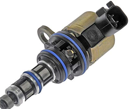 What does this OBD II code mean? This generic OBD2 code is set when the Powertrain Control Module (PCM) senses an open circuit in the control circuitry of the intake deactivation valve for cylinder #4. Why does this OBD II code appear? Modern “V” type engines, especially V8 engines, implement a strategy known as “cylinder deactivation” to enhance fuel economy. The principle is quite simple, under certain light load conditions the PCM temporarily deactivates up to 4 cylinders, imagine it as a virtual V4 engine. In order to accomplish this functionality, the engine is equipped with variable timing solenoids on the exhaust valves. Depending on the engine firing order the manufacturers configure the system to operate in a way that the driver doesn’t notice any change between modes. Since the PCM is constantly monitoring each exhaust valve control circuit voltage and/or current, any abnormality is noticed immediately. The OBD2 code P3425 is stored in memory when the PCM detects an open circuit in the control circuitry of cylinder 4 intake deactivation valve. What symptoms may occur with this OBD II code? Expect the typical symptoms from a P3425 condition: CEL lit. The Check Engine Light will turn on after few driving cycles to alert the driver about the situation. Poor fuel economy. Possible misfires and/or spark knock. What are the causes that trigger this OBD II code? There're many factors that could cause a P3425 condition including among others the following: Damaged, burnt, corroded, open or shorted solenoid wiring. Worn, corroded, burnt, disconnected or bent wiring harness connector pins. Low engine oil level Low engine oil pressure Clogged oil passage or engine mechanical condition Faulty, deficient variable timing solenoid Even when unlikely, a defective PCM cannot be discarded. Diagnostic strategy for troubleshooting this OBD II code It's highly recommended starting the diagnostic process with the usual information gathering: With the help of a professional OBD2 scan tool, preferably one with OEM capabilities, take note of all data trouble codes in memory, including pending codes. Take note of freeze frame information (if present). Query the vehicle owner about what, when and where the failure occurs. Does it happen with the engine hot? Cold? Under load? All the standard questions. Take note of the vehicle VIN and find a reliable source of technical reference. Once you are done, the next step is discarding an intermittent condition. Using your scan tool clear DTC memory. Perform a complete driving cycle according to OEM procedures. If the code P3425 disappears then inform the owner about the intermittent nature of the code and explain that further testing with the code present will be required. If the code does appear then continue to the testing stage, consisting in discarding the possible causes of the problem. IMPORTANT: the diagnostic procedure explained in this section should be taken as a guideline. Always refer to specific OEM procedures when possible. The workflow for the diagnostic process is: The tests should be executed in sequential order, in other words, complete step 1 before going to step 2 and so on. Repair, fix, or replace any component if you suspect is not in good condition. If any repair, fix, reprogramming or component replacement is made during any step then you should clear DTC memory and repeat the whole KOER driving cycle. If the DTC appear again then you should continue to the next step. If the DTC does not appear again after completing the KOER tests then you can assume the problem is fixed, in that case, continuing with the remaining steps would be optional. The diagnostic process for the code P3425 is as follows: Engine Oil Level and Condition: Verify engine oil condition and level. Perform a complete oil service if necessary. Engine Oil Pressure: using the adequate adapter and engine oil gauge, perform an engine oil pressure test. Refer to the appropriate literature to check results. In order to continue the diagnostic process, you will need to fix any issue in the engine oil system. Variable Timing Solenoid harness wiring and connector: carry out an exhaustive visual inspection of solenoid wiring and connectors. Pay special attention to burnt, corroded, open, shorted to ground or deteriorated wiring and/or connector. Unplug the solenoid and check for corrosion, damage, bent pins, etc. Electrical tests: with the help of a digital volt-ohm meter (DVOM) and the adequate wiring diagram perform a KOEO and KOER check on the solenoid. Verify supply and/or reference voltage, electrical resistance, continuity, current and ground integrity. Compare the obtained values with the appropriate OEM literature. Solenoid functional test: some manufacturers include built-in tests that help in the process of diagnosing the variable timing system, others not. Refer to the proper literature in order to perform a complete system diagnostic. The test allows you to manipulate the solenoids activation. Problems with the powertrain control module: the most unlikely cause for this code is a faulty PCM or a corrupted program. Yet, if you are completely certain that all prior tests passed then you must remove the PCM and check it, reprogram it or replace it as necessary. Do you need further help....? Discuss your car trouble code further with thousand's of car experts here Check your car problem in Vehicle Recall Section of your car brand
 -
 What does this OBD II code mean? This generic OBD2 code is set when the Powertrain Control Module (PCM) senses a voltage higher than expected in the Secondary Air Injection System (AIR) pressure sensor circuit. This particular code is pointing out the bank 2, in other words, the bank of cylinders not containing cylinder #1. Why does this OBD II code appear? The objective of the Secondary Air Injection System (AIR) is decreasing the hydrocarbon emissions under certain conditions. In order to accomplish that goal AIR inject fresh air to the exhaust system using an air pump. Besides the air pump, the AIR system uses one or more actuators (valves or solenoids) to divert the air stream as well as a pressure sensor. The OBD2 code P2438 is stored in memory when the PCM detects an AIR pressure sensor voltage higher than the acceptable limit. What symptoms may occur with this OBD II code? Expect the typical symptoms from a P2438 condition: CEL lit. The Check Engine Light will turn on after few driving cycles to alert the driver about the situation. The engine may die during idle. Possible hesitation during idle or while accelerating. Possible noise from the AIR system. What are the causes that trigger this OBD II code? There're many factors that could cause a P2438 condition including among others the following: Damaged, burnt, corroded, open or shorted AIR pressure sensor. Worn, corroded, burnt, disconnected or bent AIR pressure sensor wiring harness connector pins. Faulty or deficient AIR pressure sensor. Faulty or deficient AIR solenoids. Faulty or deficient air pump. Even when unlikely, a defective PCM cannot be discarded. Diagnostic strategy for troubleshooting this OBD II code It's highly recommended starting the diagnostic process with the usual information gathering: With the help of a professional OBD2 scan tool, preferably one with OEM capabilities, take note of all data trouble codes in memory, including pending codes. Take note of freeze frame information (if present). Query the vehicle owner about what, when and where the failure occurs. Does it happen with the engine hot? Cold? Under load? All the standard questions. Take note of the vehicle VIN and find a reliable source of technical reference. Once you are done, the next step is discarding an intermittent condition. Using your scan tool clear DTC memory. Perform a complete driving cycle according to OEM procedures. If the code P2438 disappears then inform the owner about the intermittent nature of the code and explain that further testing with the code present will be required. If the code does appear then continue to the testing stage, consisting in discarding the possible causes of the problem. IMPORTANT: the diagnostic procedure explained in this section should be taken as a guideline. Always refer to specific OEM procedures when possible. The workflow for the diagnostic process is: The tests should be executed in sequential order, in other words, complete step 1 before going to step 2 and so on. Repair, fix, or replace any component if you suspect is not in good condition. If any repair, fix, reprogramming or component replacement is made during any step then you should clear DTC memory and repeat the whole KOER driving cycle. If the DTC appear again then you should continue to the next step. If the DTC does not appear again after completing the KOER tests then you can assume the problem is fixed, in that case, continuing with the remaining steps would be optional. The diagnostic process for the code P2438 is as follows: Sensor harness wiring and connector: carry out an exhaustive visual inspection of AIR pressure sensor wiring and connectors. Pay special attention to burnt, corroded, open, shorted to ground or deteriorated wiring and/or connector. Unplug the sensor and check for corrosion, damage, bent pins, etc. Electrical tests: with the help of a digital volt-ohm meter (DVOM) and the adequate wiring diagram perform a KOEO and KOER check on the AIR pressure sensor. Verify supply and/or reference voltage, electrical resistance, continuity, current and ground integrity. Compare the obtained values with the appropriate OEM literature. AIR pressure sensor: using a scan tool you can check the sensor output. With the help of a manual vacuum pump perform a KOEO test to check its condition. Replace as necessary. AIR system functional test: some manufacturers include built-in tests that help in the process of diagnosing the AIR system, others not. Refer to the proper literature in order to perform a complete system diagnostic. The test allows you to manipulate the solenoids and air pump activation. Replace if needed. Problems with the powertrain control module: the most unlikely cause for this code is a faulty PCM or a corrupted program. Yet, if you are completely certain that all prior tests passed then you must remove the PCM and check it, reprogram it or replace it as necessary. Do you need further help....? Discuss your car trouble code further with thousand's of car experts here Check your car problem in Vehicle Recall Section of your car brand
 -
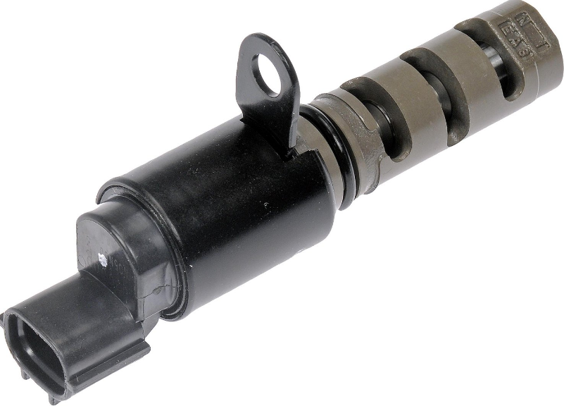 What does this OBD II code mean? This generic OBD2 code is set when the Powertrain Control Module (PCM) senses a problem in the control circuit of the deactivation valve for cylinder #4. Why does this OBD II code appear? Modern “V” type engines, especially V8 engines, implement a strategy known as “cylinder deactivation” to enhance fuel economy. The principle is quite simple, under certain light load conditions the PCM temporarily deactivates up to 4 cylinders, imagine it as a virtual V4 engine. In order to accomplish this functionality, the engine is equipped with variable timing solenoids on the exhaust valves. Depending on the engine firing order the manufacturers configure the system to operate in a way that the driver doesn’t notice any change between modes. Since the PCM is constantly monitoring each exhaust valve control circuit voltage and/or current, any abnormality is noticed immediately. The OBD2 code P3430 is stored in memory when the PCM detects a problem in the control circuit of cylinder 4. What symptoms may occur with this OBD II code? Expect the typical symptoms from a P3430 condition: CEL lit. The Check Engine Light will turn on after few driving cycles to alert the driver about the situation. Poor fuel economy. Possible misfires and/or spark knock. What are the causes that trigger this OBD II code? There're many factors that could cause a P3430 condition including among others the following: Damaged, burnt, corroded, open or shorted solenoid wiring. Worn, corroded, burnt, disconnected or bent wiring harness connector pins. Low engine oil level Low engine oil pressure Clogged oil passage or engine mechanical condition Faulty, deficient variable timing solenoid Even when unlikely, a defective PCM cannot be discarded. Diagnostic strategy for troubleshooting this OBD II code It's highly recommended starting the diagnostic process with the usual information gathering: With the help of a professional OBD2 scan tool, preferably one with OEM capabilities, take note of all data trouble codes in memory, including pending codes. Take note of freeze frame information (if present). Query the vehicle owner about what, when and where the failure occurs. Does it happen with the engine hot? Cold? Under load? All the standard questions. Take note of the vehicle VIN and find a reliable source of technical reference. Once you are done, the next step is discarding an intermittent condition. Using your scan tool clear DTC memory. Perform a complete driving cycle according to OEM procedures. If the code P3430 disappears then inform the owner about the intermittent nature of the code and explain that further testing with the code present will be required. If the code does appear then continue to the testing stage, consisting in discarding the possible causes of the problem. IMPORTANT: the diagnostic procedure explained in this section should be taken as a guideline. Always refer to specific OEM procedures when possible. The workflow for the diagnostic process is: The tests should be executed in sequential order, in other words, complete step 1 before going to step 2 and so on. Repair, fix, or replace any component if you suspect is not in good condition. If any repair, fix, reprogramming or component replacement is made during any step then you should clear DTC memory and repeat the whole KOER driving cycle. If the DTC appear again then you should continue to the next step. If the DTC does not appear again after completing the KOER tests then you can assume the problem is fixed, in that case, continuing with the remaining steps would be optional. The diagnostic process for the code P3430 is as follows: Engine Oil Level and Condition: Verify engine oil condition and level. Perform a complete oil service if necessary. Engine Oil Pressure: using the adequate adapter and engine oil gauge, perform an engine oil pressure test. Refer to the appropriate literature to check results. In order to continue the diagnostic process, you will need to fix any issue in the engine oil system. Variable Timing Solenoid harness wiring and connector: carry out an exhaustive visual inspection of solenoid wiring and connectors. Pay special attention to burnt, corroded, open, shorted to ground or deteriorated wiring and/or connector. Unplug the solenoid and check for corrosion, damage, bent pins, etc. Electrical tests: with the help of a digital volt-ohm meter (DVOM) and the adequate wiring diagram perform a KOEO and KOER check on the solenoid. Verify supply and/or reference voltage, electrical resistance, continuity, current and ground integrity. Compare the obtained values with the appropriate OEM literature. Solenoid functional test: some manufacturers include built-in tests that help in the process of diagnosing the variable timing system, others not. Refer to the proper literature in order to perform a complete system diagnostic. The test allows you to manipulate the solenoids activation. Problems with the powertrain control module: the most unlikely cause for this code is a faulty PCM or a corrupted program. Yet, if you are completely certain that all prior tests passed then you must remove the PCM and check it, reprogram it or replace it as necessary. Do you need further help....? Discuss your car trouble code further with thousand's of car experts here Check your car problem in Vehicle Recall Section of your car brand
 -
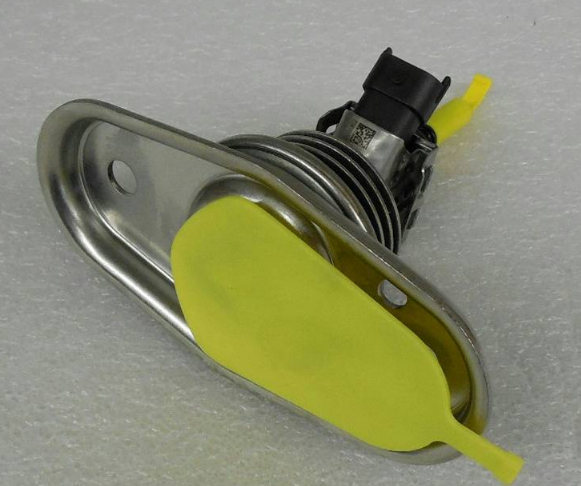 What does this OBD II code mean? This generic OBD2 code is set when the Powertrain Control Module (PCM) detects an open circuit in the reductant injection valve. This particular code is pointing out the bank 2, in other words, the bank of cylinders not containing cylinder #1. The unit 2 tag is indicating that more than one injector is used for the bank 2. Why does this OBD II code appear? On modern diesel engines, the use of an Exhaust Recirculation Valve (EGR) is not enough to fully control the amount of NOx present in the exhaust gases. That’s why the use of reductant injection systems is necessary. This system consists of one or more injectors (solenoids) commanded by the PCM that sprays a diesel exhaust fluid (DEF) just before the diesel particulate filter which in turn is part of the Selective Catalyst Reduction (SCR) system. The fluid elevates the temperature of the filter element increasing its efficiency and longevity. The injection valve solenoid only operates under certain conditions though. It’s the job of the PCM/SCR module activating this solenoid after analyzing the information from its sensors and hence helping to transform the harmful NOx emissions to nitrogen, carbon dioxide, and water. The OBD2 code P2056 is stored in memory when the PCM detects an open circuit in the solenoid valve (no voltage). What symptoms may occur with this OBD II code? Expect the typical symptoms from a P2056 condition: CEL lit. The Check Engine Light will turn on after few driving cycles to alert the driver about the situation. Possible decrease in fuel economy. Black smoke coming from the tailpipe due to NOx leftovers. What are the causes that trigger this OBD II code? There're many factors that could cause a P2056 condition including among others the following: Damaged, burnt, corroded, open or shorted injector valve wiring. Worn, corroded, burnt, disconnected or bent wiring harness connector pins. Faulty or deficient DEF injector valve solenoid. Even when unlikely, a defective PCM cannot be discarded. Please notice that possible causes are based on the assumption that only trouble code P2056 is stored in memory. Diagnostic strategy for troubleshooting this OBD II code Warning: If any other code directly related with temperature, vacuum or throttle position sensor is present then you must start diagnosing and solving those codes first. It's highly recommended starting the diagnostic process with the usual information gathering: With the help of a professional OBD2 scan tool, preferably one with OEM capabilities, take note of all data trouble codes in memory, including pending codes. Take note of freeze frame information (if present). Query the vehicle owner about what, when and where the failure occurs. Does it happen with the engine hot? Cold? Under load? All the standard questions. Take note of the vehicle VIN and find a reliable source of technical reference. Once you are done, the next step is discarding an intermittent condition. Using your scan tool clear DTC memory. Perform a complete driving cycle according to OEM procedures. If the code P2056 disappears then inform the owner about the intermittent nature of the code and explain that further testing with the code present will be required. If the code does appear then continue to the testing stage, consisting in discarding the possible causes of the problem. IMPORTANT: the diagnostic procedure explained in this section should be taken as a guideline. Always refer to specific OEM procedures when possible. The workflow for the diagnostic process is: The tests should be executed in sequential order, in other words, complete step 1 before going to step 2 and so on. Repair, fix, or replace any component if you suspect is not in good condition. If any repair, fix, reprogramming or component replacement is made during any step then you should clear DTC memory and repeat the whole KOER driving cycle. If the DTC appear again then you should continue to the next step. If the DTC does not appear again after completing the KOER tests then you can assume the problem is fixed, in that case, continuing with the remaining steps would be optional. The diagnostic process for the code P2056 is as follows: Sensor harness wiring and connector: carry out an exhaustive visual inspection of bank 2 DEF solenoid wiring and connectors. Pay special attention to burnt, corroded, open, shorted to ground or deteriorated wiring and/or connector. Unplug the solenoid and check for corrosion, damage, bent pins, etc. Electrical tests: with the help of a digital volt-ohm meter (DVOM) and the adequate wiring diagram perform a KOEO check on the DEF solenoid. Verify supply and/or reference voltage, electrical resistance, continuity, current and ground integrity. Compare the obtained values with the appropriate OEM literature. Problems with the powertrain control module: the most unlikely cause for this code is a faulty PCM or SCR module. Yet, if you are completely certain that all prior tests passed then you must remove the PCM/SCR module and check it, reprogram it or replace it as necessary. Do you need further help....? Discuss your car trouble code further with thousand's of car experts here Check your car problem in Vehicle Recall Section of your car brand
 -
P0690 ECM/PCM Power Relay Sense Circuit High
DamasoSanoja posted a OBD2 code in Computer Output Circuit Codes
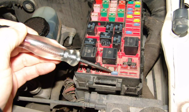 What does this OBD II code mean? This generic OBD2 code is set when the Powertrain Control Module (PCM) senses a power relay voltage higher than expected. Why does this OBD II code appear? The Power Relay is used to supply voltage to the PCM, in other words, it’s function is to deliver to the powertrain control module the adequate battery voltage needed for its operation. This contact type relay uses the traditional 5-wire design. The control circuit is activated by the ignition switch (pin 86) and the ground (pin 85). The permanent battery voltage is supplied by pin 30 as usual, and the high output voltage is delivered to the PCM by pin 87. The pin 87a is used by the PCM to monitor the relay voltage at all times. The OBD2 code P0690 is stored in memory when the PCM detects a supply voltage higher than the acceptable limit. What symptoms may occur with this OBD II code? Expect the typical symptoms from a P0690 condition: CEL lit. The Check Engine Light will turn on after few driving cycles to alert the driver about the situation. Hard start or even a no start condition. Some electrical components may not work. What are the causes that trigger this OBD II code? There're many factors that could cause a P0690 condition including among others the following: Damaged, burnt, corroded, open or shorted power relay wiring. Worn, corroded, burnt, disconnected or bent power relay wiring harness connector pins. Blown fuse (ignition circuit). Faulty or defective power relay. Even when unlikely, a defective PCM cannot be discarded. Diagnostic strategy for troubleshooting this OBD II code It's highly recommended starting the diagnostic process with the usual information gathering: With the help of a professional OBD2 scan tool, preferably one with OEM capabilities, take note of all data trouble codes in memory, including pending codes. Take note of freeze frame information (if present). Query the vehicle owner about what, when and where the failure occurs. Does it happen with the engine hot? Cold? Under load? All the standard questions. Take note of the vehicle VIN and find a reliable source of technical reference. Once you are done, the next step is discarding an intermittent condition. Using your scan tool clear DTC memory. Perform a complete driving cycle according to OEM procedures. If the code P0690 disappears then inform the owner about the intermittent nature of the code and explain that further testing with the code present will be required. If the code does appear then continue to the testing stage, consisting in discarding the possible causes of the problem. IMPORTANT: the diagnostic procedure explained in this section should be taken as a guideline. Always refer to specific OEM procedures when possible. The workflow for the diagnostic process is: The tests should be executed in sequential order, in other words, complete step 1 before going to step 2 and so on. Repair, fix, or replace any component if you suspect is not in good condition. If any repair, fix, reprogramming or component replacement is made during any step then you should clear DTC memory and repeat the whole KOER driving cycle. If the DTC appear again then you should continue to the next step. If the DTC does not appear again after completing the KOER tests then you can assume the problem is fixed, in that case, continuing with the remaining steps would be optional. The diagnostic process for the code P0690 is as follows: Relay harness wiring and connector: carry out an exhaustive visual inspection the PCM power relay wiring and connectors. Pay special attention to burnt, corroded, open, shorted to ground or deteriorated wiring and/or connector. Unplug the relay and check for corrosion, damage, bent pins, etc. Electrical tests: with the help of a digital volt-ohm meter (DVOM) and the adequate wiring diagram perform a KOEO check on the power relay. Verify the battery supply voltage and/or ignition voltage, electrical resistance, continuity, current and ground integrity. To achieve it, place one DVOM probe in a known ground (battery negative for instance) and the other in the pin 30. You should read battery voltage. Now turn the ignition switch on, engine off (KOEO). Maintain one probe in the negative terminal and use the other to measure pin 86 voltage. You should read battery voltage again if you don’t, check the corresponding fuse. Now place one probe in the terminal 30 and the other in the terminal 85. You should read the same battery voltage as before if you don’t (or is lower than 12V) then you need to check the ground line. Relay functional test: install the relay and place one DVOM probe in a known ground. With the other probe, you will measure the output from pin 87a. This pin is constantly energized, so you expect to read battery voltage unless an internal relay problem is present. Finally, turn on the switch ignition with engine off (KOEO). Read the output from pin 87, it should be 12V+. If you completed the electrical test mentioned above and the relay is not supplying the output voltage then you must replace it immediately. Problems with the powertrain control module: the most unlikely cause for this code is a faulty PCM or a corrupted program. Yet, if you are completely certain that all prior tests passed then you must remove the PCM and check it, reprogram it or replace it as necessary. Do you need further help....? Discuss your car trouble code further with thousand's of car experts here Check your car problem in Vehicle Recall Section of your car brand
 -
P200A Intake Manifold Runner Performance Bank 1
DamasoSanoja posted a OBD2 code in Fuel and Air Metering Codes
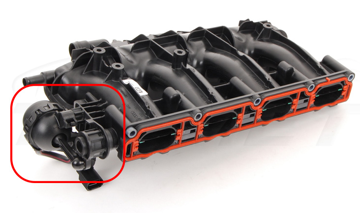 What does this OBD II code mean? This generic OBD2 code is set when the Powertrain Control Module (PCM) detects that the Intake Manifold Runner Control (IMRC) performance is outside the acceptable parameters. This particular code is pointing out the bank 1, in other words, the bank of cylinders containing cylinder #1. Why does this OBD II code appear? The Intake Manifold Runner Control (IMRC) is a system in charge of controlling the intake manifold variable airflow. Depending on the OEM, this system can vary the length of intake ports (from short to long) or simply regulate the airflow turbulence using a flap design similar to the throttle body. The goal of IMRC is prioritizing torque or power at any given operational condition. At lower RPM the IMRC helps the engine to achieve more torque, as you may infer, at higher RPM the IMRC operates in order to increase the engine power. Using this technology the manufacturers can also boost fuel economy and decrease the exhaust emissions. Some IMRC systems discriminate engine banks because they operate each one independently of the other. In order to achieve peak performance, the PCM uses information from many of its sensors. including but not limited to engine speed sensor, throttle position sensor, the throttle pedal position sensor (if applicable), and in some cases, the engine coolant. The sensors’ data allows the PCM modulating the IMRC actuators under different conditions as well as determining its performance. The OBD2 code P200A is set when the PCM senses that the intake manifold runner control is not performing as expected. What symptoms may occur with this OBD II code? The following symptoms could be present: CEL lit. The Check Engine Light will turn on after few driving cycles to alert the driver about the situation. Expect reduced engine power/torque depending on IMRC position (in case it got stuck). Also, expect a variation in fuel economy depending on IMRC condition. Engine lags under wide open throttle situations are very common. Some engine technologies may be susceptible to IMRC failures and cause rough idle, gasoline smell in the exhaust tail and even some emission related codes. What are the causes that trigger this OBD II code? There're many factors that could trigger this code including among others the following: Damaged, burnt, corroded, open or shorted IMRC wiring. Worn, corroded, burnt, disconnected or bent IMRC wiring harness connector pins. Air leaks in the intake manifold, PCV hose, vacuum hoses, vacuum driven components or MAF sensor tubing. Faulty, worn, corroded, broken or bent IMRC linkage. The majority of IMRC systems use metal flaps (similar to throttle body flap) that are linked together to control the whole bank. It’s common to find wear or corrosion in the mechanical components, especially in hot or high humidity climates. Damaged, worn, corroded or broken IMRC bushing. The normal mechanical wear produced by the constant usage of this system could cause the mechanism to “get stuck” or “partially stuck”. Think of it as the “mechanical resistance to movement” that will make very difficult to comply with PCM orders Faulty or deficient IMRC actuator (electrical or vacuum operated). The IMRC actuator is usually electro-mechanical (a servo motor electronically controlled by the PCM similar to ETC) or vacuum controlled. Either design, it’s susceptible to failure as any other moving part in the engine. Even when unlikely, a defective PCM cannot be discarded. Diagnostic strategy for troubleshooting this OBD II code It's highly recommended starting the diagnostic process with the usual information gathering: With the help of a professional OBD2 scan tool, preferably one with OEM capabilities, take note of all data trouble codes in memory, including pending codes. Take note of freeze frame information (if present). Query the vehicle owner about what, when and where the failure occurs. Does it happen with the engine hot? Cold? Under load? All the standard questions. Take note of the vehicle VIN and find a reliable source of technical reference. Once you are done, the next step is discarding an intermittent condition. Using your scan tool clear DTC memory. Perform a complete driving cycle according to OEM procedures. If the code P200A disappears then inform the owner about the intermittent nature of the code and explain that further testing with the code present will be required. If the code does appear then continue to the testing stage, consisting in discarding the possible causes of the problem. IMPORTANT: the diagnostic procedure explained in this section should be taken as a guideline. Always refer to specific OEM procedures when possible. The workflow for the diagnostic process is: The tests should be executed in sequential order, in other words, complete step 1 before going to step 2 and so on. Repair, fix, or replace any component if you suspect is not in good condition. If any repair, fix, reprogramming or component replacement is made during any step then you should clear DTC memory and repeat the whole KOER driving cycle. If the DTC appear again then you should continue to the next step. If the DTC does not appear again after completing the KOER tests then you can assume the problem is fixed, in that case, continuing with the remaining steps would be optional. The diagnostic process for the code P200A is as follows: IMRC harness wiring and connector: carry out an exhaustive visual inspection of IMRC wiring and connectors. Pay special attention to burnt, corroded or deteriorated wiring and/or connector. Unplug the actuator and check for corrosion, damage, bent pins, etc. Electrical tests: with the help of a digital volt-ohm meter (DVOM) and the adequate wiring diagram perform a KOEO check of the IMRC. Verify supply and/or reference voltage, electrical resistance, continuity, current and ground integrity. Compare the obtained values with the appropriate OEM literature. Vacuum and/or air leaks: perform a manual vacuum reading in the intake manifold test port or in any direct vacuum hose with no direct relation to the fuel injection system. If the vacuum reading is not within the normal value then perform a comprehensive visual inspection of all vacuum hoses including but not limited to PCV hose, fuel pressure regulator hose, MAP hose, brakes hose, etc, also look for intake manifold leaks and pay special attention to possible air or vacuum leaks downstream the MAF sensor. Also, check PCV and replace if defective. IMRC functional test: with the help of a professional OBD2 scan tool carry out an actuator test (sometimes called functional test). This test allows you to operate the IMRC system, depending on the vehicle year and manufacturer the test requires an engine running (KOER) condition or key on engine off (KOEO) condition. During the test pay special attention to any suspicious sound as a possible indication of internal wear. IMRC functional test (vacuum controlled): if the system is vacuum operated then check all associated vacuum lines and check valves. Using a manual vacuum pump check the actuator operation. Problems with the powertrain control module: the most unlikely cause for this code is a faulty PCM or a corrupted program. Yet, if you are completely certain that all prior tests passed then you must remove the PCM and check it, reprogram it or replace it as necessary. Do you need further help....? Discuss your car trouble code further with thousand's of car experts here Check your car problem in Vehicle Recall Section of your car brand
 -
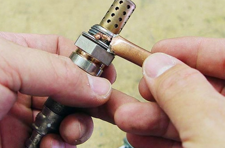 What does this OBD II code mean? This generic OBD2 code is set when the Powertrain Control Module (PCM) senses a short circuit between the O2 sensor signal and the heater element circuit. This particular code is pointing out the bank 1, in other words, the bank of cylinders containing cylinder #1. The sensor 3 tag is indicating the downstream O2 sensor located just after the last catalytic converter. Why does this OBD II code appear? Most of these oxygen sensors use a 4-wire circuit, but 3-wire circuits and in some cases 5+ wire circuits are also used. What all of them have in common is the “heater circuit”. The heater element helps the sensor to reach its operating temperature faster. The PCM is constantly monitoring the heater circuit, specifically its voltage and/or current. Depending on the year and vehicle maker, the heater circuit can be commanded by the supply voltage (positively controlled) or by the ground circuit (negatively controlled). In both cases, the powertrain control module (PCM) is in charge of activating the circuit when considered necessary. Because of that, the PCM can compare in real time the heater circuit voltage (or current depending on design) with a reference value that its no other than the vehicle operating voltage. Usually, a discrepancy greater than 10% is enough to alert the PCM about a potential short. The OBD2 code P2233 is stored in memory when the PCM detects a short in the sensor signal with the heater element circuit for bank 1, sensor 3. What symptoms may occur with this OBD II code? Expect the typical symptoms from a P2233 code: CEL lit. The Check Engine Light will turn on after few driving cycles to alert the driver about the situation. What are the causes that trigger this OBD II code? There're many factors that could cause a code P2233 including among others the following: Damaged, burnt, corroded, open or shorted downstream O2 sensor wiring. Worn, corroded, burnt, disconnected or bent downstream O2 wiring harness connector pins. Damaged or deficient heater circuit relay or fuse (usually only positively controlled systems) Faulty or deficient downstream oxygen sensor. Even when unlikely, a defective PCM cannot be discarded. Diagnostic strategy for troubleshooting this OBD II code Warning: If any other code directly related with the upstream oxygen sensor is present then you must start diagnosing and solving those codes first. It's highly recommended starting the diagnostic process with the usual information gathering: With the help of a professional OBD2 scan tool, preferably one with OEM capabilities, take note of all data trouble codes in memory, including pending codes. Take note of freeze frame information (if present). Query the vehicle owner about what, when and where the failure occurs. Does it happen with the engine hot? Cold? Under load? All the standard questions. Take note of the vehicle VIN and find a reliable source of technical reference. Once you are done, the next step is discarding an intermittent condition. Using your scan tool clear DTC memory. Perform a complete driving cycle according to OEM procedures. If the code P2233 disappears then inform the owner about the intermittent nature of the code and explain that further testing with the code present will be required. If the code does appear then continue to the testing stage, consisting in discarding the possible causes of the problem. IMPORTANT: the diagnostic procedure explained in this section should be taken as a guideline. Always refer to specific OEM procedures when possible. The workflow for the diagnostic process is: The tests should be executed in sequential order, in other words, complete step 1 before going to step 2 and so on. Repair, fix, or replace any component if you suspect is not in good condition. If any repair, fix, reprogramming or component replacement is made during any step then you should clear DTC memory and repeat the whole KOER driving cycle. If the DTC appear again then you should continue to the next step. If the DTC does not appear again after completing the KOER tests then you can assume the problem is fixed, in that case, continuing with the remaining steps would be optional. The diagnostic process for the code P2233 is as follows: Sensor harness wiring and connector: carry out an exhaustive visual inspection of bank 1 downstream oxygen sensor wiring and connectors. Pay special attention to burnt, corroded, open, shorted to ground or deteriorated wiring and/or connector. Unplug the sensor and check for corrosion, damage, bent pins, etc. Heater circuit relay/fuse: on systems with a positively controlled heater circuit is not uncommon to find a relay and/or fuse as part of the circuit. Check its condition and replace as necessary. Electrical tests: with the help of a digital volt-ohm meter (DVOM) and the adequate wiring diagram perform a KOEO and KOER check on the heater circuit for the bank 1 downstream O2 sensor. Verify supply and/or reference voltage, electrical resistance, continuity, current and ground integrity. Compare the obtained values with the appropriate OEM literature. It’s crucial during this stage to perform the adequate tests depending on circuitry design (positively controlled or negatively controlled). Downstream oxygen sensor: some manufacturers include built-in tests that help in the process of diagnosing the O2 sensor, others not. Refer to the proper literature in order to perform a complete sensor diagnostic. Replace if needed. As usual, after any repair clear the DTC memory, repeat KOER driving cycle and check if the code persists. If the code appears again then continue with the next step. Problems with the powertrain control module: the most unlikely cause for this code is a faulty PCM or a corrupted program. Yet, if you are completely certain that all prior tests passed then you must remove the PCM and check it, reprogram it or replace it as necessary. Do you need further help....? Discuss your car trouble code further with thousand's of car experts here Check your car problem in Vehicle Recall Section of your car brand
 -
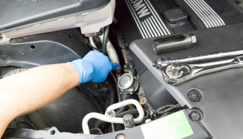 What does this OBD II code mean? This generic OBD2 code is set when the Powertrain Control Module (PCM) senses a short circuit between the O2 sensor signal and the heater element circuit. This particular code is pointing out the bank 2, in other words, the bank of cylinders not containing cylinder #1. The sensor 1 tag is indicating the upstream O2 sensor located just after the catalytic converter. Why does this OBD II code appear? Most of these oxygen sensors use a 4-wire circuit, but 3-wire circuits and in some cases 5+ wire circuits are also used. What all of them have in common is the “heater circuit”. The heater element helps the sensor to reach its operating temperature faster. The PCM is constantly monitoring the heater circuit, specifically its voltage and/or current. Depending on the year and vehicle maker, the heater circuit can be commanded by the supply voltage (positively controlled) or by the ground circuit (negatively controlled). In both cases, the powertrain control module (PCM) is in charge of activating the circuit when considered necessary. Because of that, the PCM can compare in real time the heater circuit voltage (or current depending on design) with a reference value that its no other than the vehicle operating voltage. Usually, a discrepancy greater than 10% is enough to alert the PCM about a potential short. The OBD2 code P2234 is stored in memory when the PCM detects a short in the sensor signal with the heater element circuit for bank 2, sensor 1. What symptoms may occur with this OBD II code? Expect the typical symptoms from a P2234 code: CEL lit. The Check Engine Light will turn on after few driving cycles to alert the driver about the situation. Poor fuel economy Possible misfires, spark knocking or detonations. Possible rough idle and/or engine hesitation. Sometimes you may expect a lack of power, especially during hard acceleration. In general, expect any condition directly related to an incorrect air-fuel mixture. What are the causes that trigger this OBD II code? There're many factors that could cause a code P2234 including among others the following: Damaged, burnt, corroded, open or shorted upstream O2 sensor wiring. Worn, corroded, burnt, disconnected or bent upstream O2 wiring harness connector pins. Damaged or deficient heater circuit relay or fuse (usually only positively controlled systems) Faulty or deficient upstream oxygen sensor. Even when unlikely, a defective PCM cannot be discarded. Diagnostic strategy for troubleshooting this OBD II code Warning: If any other code directly related with the upstream oxygen sensor is present then you must start diagnosing and solving those codes first. It's highly recommended starting the diagnostic process with the usual information gathering: With the help of a professional OBD2 scan tool, preferably one with OEM capabilities, take note of all data trouble codes in memory, including pending codes. Take note of freeze frame information (if present). Query the vehicle owner about what, when and where the failure occurs. Does it happen with the engine hot? Cold? Under load? All the standard questions. Take note of the vehicle VIN and find a reliable source of technical reference. Once you are done, the next step is discarding an intermittent condition. Using your scan tool clear DTC memory. Perform a complete driving cycle according to OEM procedures. If the code P2234 disappears then inform the owner about the intermittent nature of the code and explain that further testing with the code present will be required. If the code does appear then continue to the testing stage, consisting in discarding the possible causes of the problem. IMPORTANT: the diagnostic procedure explained in this section should be taken as a guideline. Always refer to specific OEM procedures when possible. The workflow for the diagnostic process is: The tests should be executed in sequential order, in other words, complete step 1 before going to step 2 and so on. Repair, fix, or replace any component if you suspect is not in good condition. If any repair, fix, reprogramming or component replacement is made during any step then you should clear DTC memory and repeat the whole KOER driving cycle. If the DTC appear again then you should continue to the next step. If the DTC does not appear again after completing the KOER tests then you can assume the problem is fixed, in that case, continuing with the remaining steps would be optional. The diagnostic process for the code P2234 is as follows: Sensor harness wiring and connector: carry out an exhaustive visual inspection of bank 2 upstream oxygen sensor wiring and connectors. Pay special attention to burnt, corroded, open, shorted to ground or deteriorated wiring and/or connector. Unplug the sensor and check for corrosion, damage, bent pins, etc. Heater circuit relay/fuse: on systems with a positively controlled heater circuit is not uncommon to find a relay and/or fuse as part of the circuit. Check its condition and replace as necessary. Electrical tests: with the help of a digital volt-ohm meter (DVOM) and the adequate wiring diagram perform a KOEO and KOER check on the heater circuit for the bank 2 upstream O2 sensor. Verify supply and/or reference voltage, electrical resistance, continuity, current and ground integrity. Compare the obtained values with the appropriate OEM literature. It’s crucial during this stage to perform the adequate tests depending on circuitry design (positively controlled or negatively controlled). Upstream oxygen sensor: some manufacturers include built-in tests that help in the process of diagnosing the O2 sensor, others not. Refer to the proper literature in order to perform a complete sensor diagnostic. Replace if needed. As usual, after any repair clear the DTC memory, repeat KOER driving cycle and check if the code persists. If the code appears again then continue with the next step. Problems with the powertrain control module: the most unlikely cause for this code is a faulty PCM or a corrupted program. Yet, if you are completely certain that all prior tests passed then you must remove the PCM and check it, reprogram it or replace it as necessary. Do you need further help....? Discuss your car trouble code further with thousand's of car experts here Check your car problem in Vehicle Recall Section of your car brand
 -
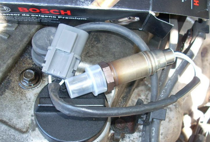 What does this OBD II code mean? This generic OBD2 code is set when the Powertrain Control Module (PCM) senses a short circuit between the O2 sensor signal and the heater element circuit. This particular code is pointing out the bank 2, in other words, the bank of cylinders not containing cylinder #1. The sensor 2 tag is indicating the downstream O2 sensor located just after the catalytic converter. Why does this OBD II code appear? Most of these oxygen sensors use a 4-wire circuit, but 3-wire circuits and in some cases 5+ wire circuits are also used. What all of them have in common is the “heater circuit”. The heater element helps the sensor to reach its operating temperature faster. The PCM is constantly monitoring the heater circuit, specifically its voltage and/or current. Depending on the year and vehicle maker, the heater circuit can be commanded by the supply voltage (positively controlled) or by the ground circuit (negatively controlled). In both cases, the powertrain control module (PCM) is in charge of activating the circuit when considered necessary. Because of that, the PCM can compare in real time the heater circuit voltage (or current depending on design) with a reference value that its no other than the vehicle operating voltage. Usually, a discrepancy greater than 10% is enough to alert the PCM about a potential short. The OBD2 code P2235 is stored in memory when the PCM detects a short in the sensor signal with the heater element circuit for bank 2, sensor 2. What symptoms may occur with this OBD II code? Expect the typical symptoms from a P2235 code: CEL lit. The Check Engine Light will turn on after few driving cycles to alert the driver about the situation. What are the causes that trigger this OBD II code? There're many factors that could cause a code P2235 including among others the following: Damaged, burnt, corroded, open or shorted downstream O2 sensor wiring. Worn, corroded, burnt, disconnected or bent downstream O2 wiring harness connector pins. Damaged or deficient heater circuit relay or fuse (usually only positively controlled systems) Faulty or deficient downstream oxygen sensor. Even when unlikely, a defective PCM cannot be discarded. Diagnostic strategy for troubleshooting this OBD II code Warning: If any other code directly related with the upstream oxygen sensor is present then you must start diagnosing and solving those codes first. It's highly recommended starting the diagnostic process with the usual information gathering: With the help of a professional OBD2 scan tool, preferably one with OEM capabilities, take note of all data trouble codes in memory, including pending codes. Take note of freeze frame information (if present). Query the vehicle owner about what, when and where the failure occurs. Does it happen with the engine hot? Cold? Under load? All the standard questions. Take note of the vehicle VIN and find a reliable source of technical reference. Once you are done, the next step is discarding an intermittent condition. Using your scan tool clear DTC memory. Perform a complete driving cycle according to OEM procedures. If the code P2235 disappears then inform the owner about the intermittent nature of the code and explain that further testing with the code present will be required. If the code does appear then continue to the testing stage, consisting in discarding the possible causes of the problem. IMPORTANT: the diagnostic procedure explained in this section should be taken as a guideline. Always refer to specific OEM procedures when possible. The workflow for the diagnostic process is: The tests should be executed in sequential order, in other words, complete step 1 before going to step 2 and so on. Repair, fix, or replace any component if you suspect is not in good condition. If any repair, fix, reprogramming or component replacement is made during any step then you should clear DTC memory and repeat the whole KOER driving cycle. If the DTC appear again then you should continue to the next step. If the DTC does not appear again after completing the KOER tests then you can assume the problem is fixed, in that case, continuing with the remaining steps would be optional. The diagnostic process for the code P2235 is as follows: Sensor harness wiring and connector: carry out an exhaustive visual inspection of bank 2 downstream oxygen sensor wiring and connectors. Pay special attention to burnt, corroded, open, shorted to ground or deteriorated wiring and/or connector. Unplug the sensor and check for corrosion, damage, bent pins, etc. Heater circuit relay/fuse: on systems with a positively controlled heater circuit is not uncommon to find a relay and/or fuse as part of the circuit. Check its condition and replace as necessary. Electrical tests: with the help of a digital volt-ohm meter (DVOM) and the adequate wiring diagram perform a KOEO and KOER check on the heater circuit for the bank 2 downstream O2 sensor. Verify supply and/or reference voltage, electrical resistance, continuity, current and ground integrity. Compare the obtained values with the appropriate OEM literature. It’s crucial during this stage to perform the adequate tests depending on circuitry design (positively controlled or negatively controlled). Downstream oxygen sensor: some manufacturers include built-in tests that help in the process of diagnosing the O2 sensor, others not. Refer to the proper literature in order to perform a complete sensor diagnostic. Replace if needed. As usual, after any repair clear the DTC memory, repeat KOER driving cycle and check if the code persists. If the code appears again then continue with the next step. Problems with the powertrain control module: the most unlikely cause for this code is a faulty PCM or a corrupted program. Yet, if you are completely certain that all prior tests passed then you must remove the PCM and check it, reprogram it or replace it as necessary. Do you need further help....? Discuss your car trouble code further with thousand's of car experts here Check your car problem in Vehicle Recall Section of your car brand
 -
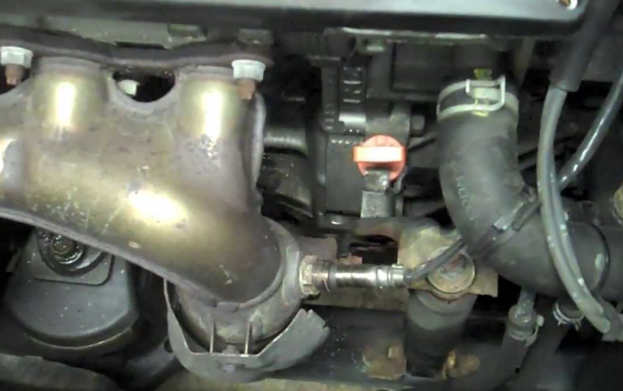 What does this OBD II code mean? This generic OBD2 code is set when the Powertrain Control Module (PCM) senses that the upstream oxygen sensor positive circuit is open. This particular code is pointing out the bank 1, in other words, the bank of cylinders containing cylinder #1. The sensor 1 tag is indicating the upstream O2 sensor located just before the catalytic converter. Why does this OBD II code appear? Most of the oxygen sensors use a 4-wire circuit, but 3-wire circuits and in some cases 5+ wire circuits are also used. What all of them have in common is the “heater circuit”. The heater element helps the sensor to reach its operating temperature faster. The PCM is constantly monitoring the heater circuit, specifically its voltage and/or current. Depending on the year and vehicle maker, the heater circuit can be commanded by the supply voltage (positively controlled) or by the ground circuit (negatively controlled). In both cases, the powertrain control module (PCM) is in charge of activating the circuit when considered necessary. Because of that, the PCM can compare in real time the heater circuit voltage (or current depending on design) with a reference value that it's no other than the vehicle operating voltage. Usually, a discrepancy greater than 10% is enough to alert the PCM about a potential short or open circuit. The OBD2 code P2238 is stored in memory when the PCM detects a voltage lower than the expected in the positive circuit line used for control. Depending on the year of the vehicle, manufacturer and the sensor design the positive line may have a relay and a fuse. Those elements may also trigger this code. What symptoms may occur with this OBD II code? Expect the typical symptoms from a P2238 code: CEL lit. The Check Engine Light will turn on after few driving cycles to alert the driver about the situation. Poor fuel economy Possible misfires, spark knocking or detonations. Possible rough idle and/or engine hesitation. Sometimes you may expect a lack of power, especially during hard acceleration. In general, expect any condition directly related to an incorrect air-fuel mixture. What are the causes that trigger this OBD II code? There're many factors that could cause a code P2238 including among others the following: Damaged, burnt, corroded, open or shorted upstream O2 sensor wiring. Worn, corroded, burnt, disconnected or bent upstream O2 wiring harness connector pins. Damaged or deficient heater circuit relay or fuse (usually only positively controlled systems) Faulty or deficient upstream oxygen sensor. Even when unlikely, a defective PCM cannot be discarded. Diagnostic strategy for troubleshooting this OBD II code Warning: If any other code directly related with the upstream oxygen sensor is present then you must start diagnosing and solving those codes first. It's highly recommended starting the diagnostic process with the usual information gathering: With the help of a professional OBD2 scan tool, preferably one with OEM capabilities, take note of all data trouble codes in memory, including pending codes. Take note of freeze frame information (if present). Query the vehicle owner about what, when and where the failure occurs. Does it happen with the engine hot? Cold? Under load? All the standard questions. Take note of the vehicle VIN and find a reliable source of technical reference. Once you are done, the next step is discarding an intermittent condition. Using your scan tool clear DTC memory. Perform a complete driving cycle according to OEM procedures. If the code P2238 disappears then inform the owner about the intermittent nature of the code and explain that further testing with the code present will be required. If the code does appear then continue to the testing stage, consisting in discarding the possible causes of the problem. IMPORTANT: the diagnostic procedure explained in this section should be taken as a guideline. Always refer to specific OEM procedures when possible. The workflow for the diagnostic process is: The tests should be executed in sequential order, in other words, complete step 1 before going to step 2 and so on. Repair, fix, or replace any component if you suspect is not in good condition. If any repair, fix, reprogramming or component replacement is made during any step then you should clear DTC memory and repeat the whole KOER driving cycle. If the DTC appear again then you should continue to the next step. If the DTC does not appear again after completing the KOER tests then you can assume the problem is fixed, in that case, continuing with the remaining steps would be optional. The diagnostic process for the code P2238 is as follows: Sensor harness wiring and connector: carry out an exhaustive visual inspection of bank 1 upstream oxygen sensor wiring and connectors. Pay special attention to burnt, corroded, open, shorted to ground or deteriorated wiring and/or connector. Unplug the sensor and check for corrosion, damage, bent pins, etc. Electrical tests: with the help of a digital volt-ohm meter (DVOM) and the adequate wiring diagram perform a KOEO and KOER check on the heater circuit for the bank 1 upstream O2 sensor. Verify supply and/or reference voltage, electrical resistance, continuity, current and ground integrity. Compare the obtained values with the appropriate OEM literature. It’s crucial during this stage to perform the adequate tests depending on circuitry design (positively controlled or negatively controlled). Heater Circuit Relay and Fuse: on some vehicles, you may find a relay that is controlled by the PCM to operate the heater element circuit. If that’s the case, check the condition of the relay and its fuse. Replace as necessary. Upstream oxygen sensor: some manufacturers include built-in tests that help in the process of diagnosing the O2 sensor, others not. Refer to the proper literature in order to perform a complete sensor diagnostic. Replace if needed. As usual, after any repair clear the DTC memory, repeat KOER driving cycle and check if the code persists. If the code appears again then continue with the next step. Problems with the powertrain control module: the most unlikely cause for this code is a faulty PCM or a corrupted program. Yet, if you are completely certain that all prior tests passed then you must remove the PCM and check it, reprogram it or replace it as necessary. Do you need further help....? Discuss your car trouble code further with thousand's of car experts here Check your car problem in Vehicle Recall Section of your car brand